“The sooner you start to code, the longer the program will take.” – Roy Carlson
Summary
In this tutorial, we introduce Approachable interaction with hardware using an Arduino powered device. We will use the LED on the Arduino to demonstrate a hardware scenario where the desire is to turn a light on and off.
Materials
- Android Phone
- Approachable-Sandbox App
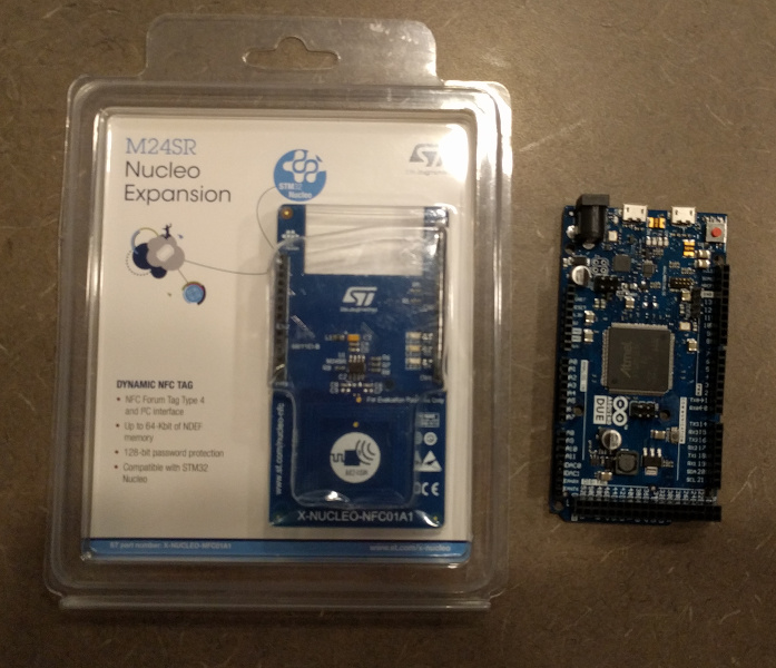
- Arduino Due (other Arduinos should be easy to adapt as well)
- ST Micro M24SR Arduino Board
Procedure
Step 1 - Creating an Approachable Interface Manifest
Since we are trying to manipulate an LED on the Arduino, we will want it to change in response to a message that looks something like this;
Desired Result from phone to device
{
   "schema_id": "LED Input",
   "LED State":"On"
}
Just as in tutorial 1, we will use the manifest skeleton.
### Manifest Skeleton
{
    "i": "",
    "name": "Wifi Device",
    "tasks": [
    ],
    "diagnostics" : [
    ]
}
We will then expand the skeleton to include a task that will be used for changing the device state, and a diagnostic that will be used to display the current state of the device when scanned. The final manifest will look like this.
Manifest
{
   "i": "",
   "name": "Illumation Device",
   "tasks": [
      {
         "name": "Light Settings",
         "schema_id": "LED Input",
         "schema": {
            "type": "object",
            "properties": {
               "LED State": {
                  "enum": [
                     "On",
                     "Off"
                  ],
                  "required": true
               }
            }
         },
         "options": {
            "fields": {
               "LED State": {
                  "type": "radio",
                  "label": "Light Switch",
                  "showMessages": false,
                  "hideInitValidationError": true
               }
            }
         }
      }
   ],
   "diagnostics": [
      {
         "schema_id": "LED output",
         "schema": {
            "title": "status",
            "type": "object",
            "properties": {
               "LED State": {
                  "title": "Light Is Currently: ",
                  "type": "string"
               }
            }
         },
         "data": {
            "LED State": "Unknown"
         }
      }
   ]
}
Step 2 - Registering With the Approchable Device Registry
Following the same steps as Tutorial 1, we head over to our Developer Sandbox version of the Approachable Device Registry.
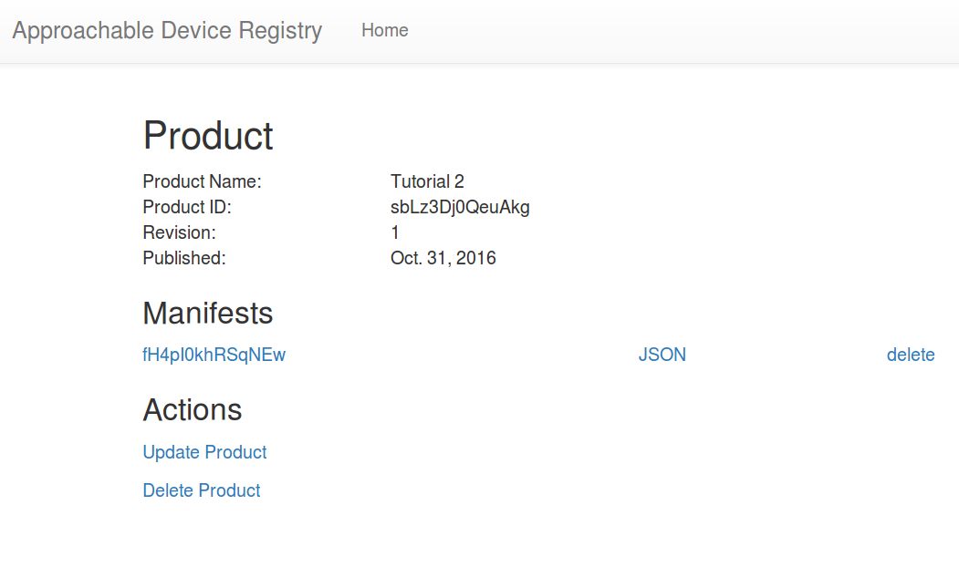
We create a new product and then a manifest for our product where we upload our previously created manifest. The registry will assign an interface identifer “i” to our product. In the below picture it is the value “fH4pI0khRSqNEw”. Your value will be different
Step 3 - Arduino Setup
Git clone our library for using the M24SR Tag with Arduino.
git clone --recursive https://bitbucket.org/approachable/m24sr-arduino.git
The recursive flag is necessary to automatically pull in some of the libraries that are git submodules.
Copy the examples and libraries of the repository into your Arduino folder.
Make sure you are using a recent enough version of the Arduino IDE. We tested this on 1.6.7. Start the IDE and with the library manager, find and install Arduinojson. Open the example approachable-LED.ino that was copied into your sketchbook and verify that it compiles for the Arduino Due or other target board.
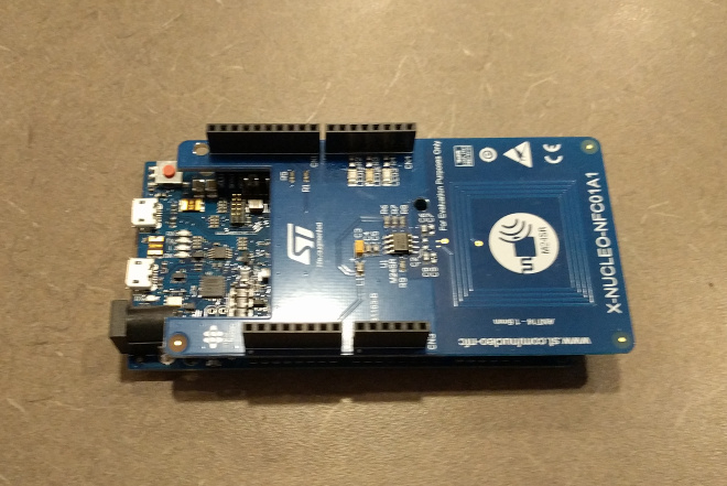
Mount the NFC shield on your Arduino and plug the Arduino into your USB.
Step 4 - Modify the Code
approachable-LED.ino is designed to turn the LED of the arduino on and off based on input from the smartphone user. When it receives data over NFC, it will disable the RF interface and read in the tag data over the i2c bus. If the data can be read and interpreted as valid and useful JSON, the LED will be turned on or off based on the value of “LED State”.
We won’t cover the code and libraries in great detail here, just the basics. The uC must perform two main functions. * Read data from the NFC tag over the i2c bus when it is written to by the NFC writer and update the state of the LED accordingly. This is accomplished by the process_nfc and process_JSON functions. * Ensure that the tag is reporting the current state of the device via the NFC tag. This is accomplished by the update_status function.
Everything else is just standard setup and loop functions. More complex procedures such as interrupt handling are accomplished in the included libraries.
There is only one part of the code that you need to change. Locate the following Macro defining MANIFEST_ID.
#define MANIFEST_ID "fH4pI0khRSqNEw"
replace the value with the interface identifier “i” that was set by the Device Registry in Step 2.
NOTE: This demo is readily adapted to other Arduino boards by updating the driver settings in drv_I2C_M24SR.h. Here, the GPO and RFDIS pins can be changed, but the GPO must be used with an interrupt capable pin.
Step 5 - Compile and Test
You should now be able to compile the code and flash it to the Due board. The serial output can be monitored for some diagnostic output.
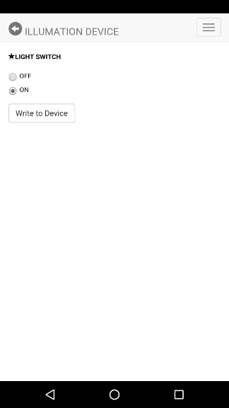
Leave the Board and shield powered and using your phone, while set to its home screen, Perform an NFC scan of the shield. You should be presented with this interface.
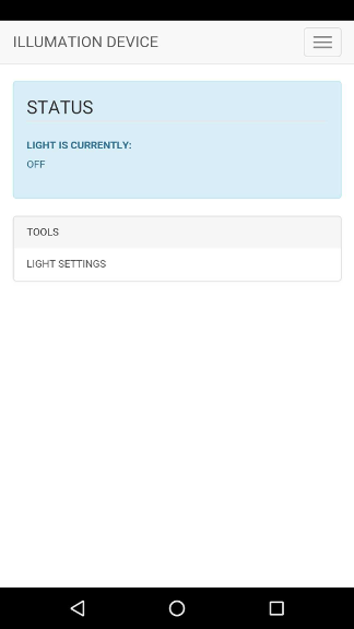
The interface and tool were automatically contructed from your manifest. When the phone pulled the manifest id off of the NFC tag, it queried the device registry in order to retrieve the manifest that you constructed.
Notice the diagnostic display which should report the Light state as “Off”.
Use the “Light Settings” tool and choose to turn the light on. When prompted, touch your phone to the NFC antenna to write this state change to the NFC tag. An LED on your board should turn on. On the Due, this LED is marked “L” and is located next to the power LED.
Now exit the app and repeat the process. This time you should see that the device reports the Light state as “On”. When you change the Light Settings this time, choose to turn the LED off and you should observe the LED being turned off.